Function of PV Combiner Box-Blog
DATE:2021-08-17
In order to better understand the PV combiner box, the photovoltaic AC combiner box will be introduced from the aspects of combiner box function introduction, display, technical parameters, wiring schematic diagram, installation tools, installation precautions, wiring and so on.
During commissioning, operation and maintenance, pv combiner box failures accounted for 20-30% of the cause of the failure of the entire power station. Unsafe combiner boxes are easy to cause fires and seriously threaten property and personal safety.
Product function introduction of photovoltaic combiner box
• The photovoltaic AC combiner box adopts a photovoltaic power generation system with string inverters and is installed between the AC output side of the inverter and the grid connection point/load.
• Internally equipped with input circuit breaker, output circuit breaker, AC lightning protection device, and optional intelligent monitoring instrument (monitoring system voltage, current, power, energy and other signals)
• Main function: converge the output current of multiple inverters, protect the inverters from the AC grid-connected side/load at the same time, as the inverter output disconnection point, improve the safety of the system, and protect the installation and maintenance personnel Security.
Solar combiner box product display
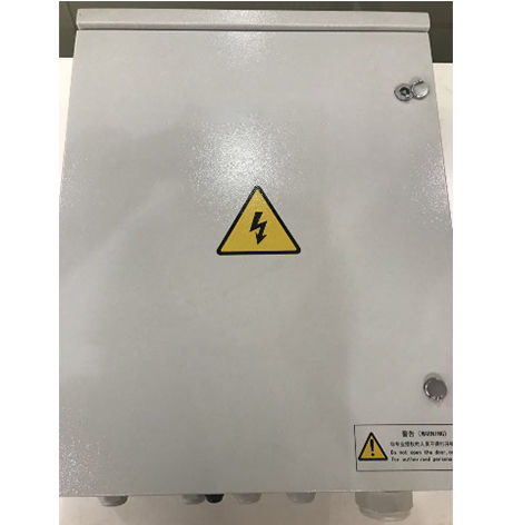
Take the AC combiner box (400V/50KW) with 4 sinks and 1 as an example, there are 4 sets of 50KW inverters:
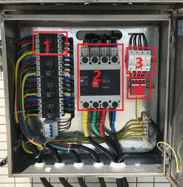
Label 1: The output of the inverter is directly connected to the 4P circuit breaker. The circuit breaker can quickly cut off the fault current. The maximum AC output current of the inverter is 80A. The air switch specification is 1.25 times the maximum current of the inverter, and 100A is selected. Molded case circuit breaker.
Label 2: The total circuit breaker after the three inverters converge is a molded case circuit breaker with a rated current of 350A. The cables connected to the circuit breaker are connected by copper bars with a wire diameter of 150mm².
Mark 3: The fuse (insurance) is an overcurrent protector. When the current of the protected circuit exceeds the specified value, the fuse will be blown and the circuit will be disconnected to protect it. Generally, it will act after the lightning surge fails. , You can choose a 100A fuse.
Label 4: Surge protector is used to suppress transient overvoltage lower than the equipment withstand impulse overvoltage, discharge the surge energy, thereby protecting the system circuit and equipment. Specification Uc: 750V Imax: 40KA In: 20KA Up≤2.6KV, the underside of the surge must be grounded.
Technical Parameters of Photovoltaic Combiner Box
• Technical parameters of AC combiner box
| Performance parameter | Input voltage range [VAC] | 0-690V |
| Maximum working voltage [VAC] | ≤690 | |
| Maximum input current per channel [A] | 100A | |
| Parallel input channels | 4 | |
| Maximum output current (A) | 400 | |
| Certification status | 3C | |
| Component parameters | Input wiring cross-sectional area | ZC-YJV-0.6/1KV 3X35mm2 |
| Output cable cross-sectional area [mm2] | ZC-YJV-0.6/1KV 3X185mm2 | |
| Number of output connections | 1 output, 1 ground | |
| Ground wire diameter [mm2] | The protective grounding conductor of the fixed connection is larger than 10 square (copper) | |
| Appearance information | Shell information | 1.5 thick galvanized steel sheet |
| Protection level | IP65 | |
| Environmental requirements | Storage environment temperature requirements ['C] | -40°C~+70°C |
| Use environment temperature requirement [°C] | -25°C~ +50*C | |
| altitude | s2000m |
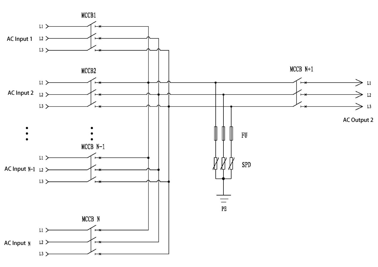
Wiring schematic diagram of photovoltaic AC combiner box
Precautions for installation of photovoltaic pv combiner box
The protection level of the cabinet is IP65, which is suitable for outdoor installation. The installation position should meet the following requirements:
The overall size and weight of the combiner box should be fully considered according to the position (refer to the parameter chapter)
The installation environment temperature of the combiner box should be between -25℃`+60℃, and the relative humidity should be between 0-95%
The combiner box should be installed in a dry, well-ventilated and dust-proof place
Wire entry and exit type and installation method: the armored cable enters and exits from the bottom, and the outdoor photovoltaic module bracket is suspended and installed on the rear column.
Avoid installing in a place directly exposed to the sun, otherwise excessively high temperature will reduce the power generation of the system and may also affect the service life of the combiner box
In order to better dissipate heat and facilitate daily maintenance, keep enough space in the four directions for installing the combiner box
Volt AC combiner box wiring
Photovoltaic AC combiner box wiring
Preparation before wiring
1. Open the combiner box
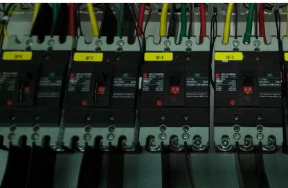
2. Put all MCCBs in the trip state
Input wiring
1. Connect according to the wiring schematic diagram, and confirm the phase sequence and confirm that there is no ground fault before wiring;
2. Loosen the tightening nut of the lower waterproof terminal of the combiner box;
3. Pass the input cable through the white cable connector, and leave a margin for the cable length so that the inside of the combiner box can be bent and fixed;
4. Crimp the wiring nose;
5. Use a No. 6 hex wrench to put 3 sets of M8 on the input end of the circuit breaker;
The hexagon socket screws are loosened, the input terminals of the circuit breaker are connected in the order of three-phase yellow from left to right, and 6 groups of input wires are connected, M8 torque 11N.m

6. Tighten the tightening nut of the incoming cable connector.
Output wiring (recommended)
Tools: crimping pliers; long-handled Phillips screwdriver; M10 hexagon socket wrench (M6)
1. The output terminal connection method of the combiner box is similar to the input connection method. Strip the cable and put the copper nose on the stripped wire

2. Use a crimping tool to crimp
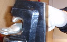
3. Set the corresponding heat shrinkable tube, the positive pole is red, the negative pole is black
4. Loosen the waterproof connector, turn it counterclockwise, and pass the wire through the cable connector
5. Connect the completed wire to the copper bar at the output end of the circuit breaker. Tighten the M10 screw (torque 25N.m) on the output end, and then make the wire neat and flat
6. Tighten the waterproof connector clockwise

